

Introduction
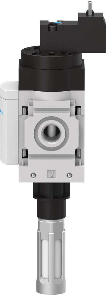
A Festo Pneumatic Control Valve manages how compressed air enters, leaves, or changes direction within an automated machine. It allows cylinders, grippers, slides, clamps, and rotary actuators to perform controlled movements according to electrical, pneumatic, mechanical, or manual commands.
The correct control valve can improve movement accuracy, cycle consistency, maintenance access, and energy use. However, engineers must match its function, flow capacity, pressure range, connections, and resting position to the complete pneumatic circuit.
What Is a Festo Pneumatic Control Valve?
A pneumatic control valve opens, closes, restricts, or redirects compressed-air passages. Its internal spool, poppet, diaphragm, or sealing element changes position when it receives an operating signal.
Festo provides pneumatically and electrically actuated directional-control valves in compact and robust designs. The available products differ in valve construction, switching positions, flow paths, and actuation methods, allowing them to serve varied automation requirements.
How Does a Pneumatic Control Valve Create Motion?
Compressed air enters through the supply connection. The valve then directs it towards one actuator chamber while connecting another chamber to exhaust.
This pressure difference produces mechanical movement. When the valve switches again, the airflow path changes and the actuator either reverses direction, stops, releases, or returns to its original position.
Suitable Pneumatic Function Fittings can add specialised airflow behaviour at selected points within the circuit.
Which Directional Valve Functions Are Common?
2/2-Way Operation
A 2/2-way valve has two ports and two positions. It normally starts or stops airflow through a single pneumatic route.
This function suits isolation, supply control, and straightforward air-on or air-off applications.
3/2-Way Operation
A 3/2-way valve includes three ports and two switching positions. It is frequently used with single-acting cylinders, pneumatic signals, and devices that need one working port with supply and exhaust paths.
5/2-Way Operation
A 5/2-way valve has five ports and two positions. It commonly controls a double-acting actuator by supplying one chamber while exhausting the other.
Festo’s universal directional-control portfolio includes several 3/2 and 5/2 configurations, including compact VUVG and robust VUVS valve families.
5/3-Way Operation
A 5/3-way valve provides a centre position in addition to two directional states. Depending on the selected design, the centre may block, exhaust, or pressurise the working ports.
The centre condition must be selected according to load behaviour, stored pressure, actuator type, and machine safety requirements.
How Are Festo Control Valves Actuated?
Electrical Actuation
A solenoid-operated valve receives voltage from a controller or switching device. The energised coil produces magnetic force that moves an armature or pilot stage.
Electrical control supports remote operation, automatic sequencing, and integration with machine sensors.
Pneumatic Actuation
A pneumatically actuated valve changes position when it receives a pilot-air signal. This method can support equipment where electrical components are unsuitable or where pneumatic logic already manages the sequence.
Compatible Pneumatic Logic Element Function Fittings can perform selected logical functions within air-operated control circuits.
Mechanical and Manual Actuation
Mechanical valves may use rollers, plungers, or levers that respond to machine movement. Manual models use buttons, pedals, selectors, or hand levers.
These options are useful for setup, clamping stations, test equipment, and applications where direct operator control is required.
Where Are Pneumatic Control Valves Used?
Assembly Equipment
Assembly machinery uses control valves for pressing, clamping, ejecting, locating, and transferring components. The valve must switch at the correct point in the sequence to avoid collisions or incomplete assembly.
Packaging Machinery
Packaging systems require repeatable pneumatic motion for sealing, cutting, guiding, lifting, diverting, and rejecting products.
Material-Handling Systems
Control valves operate grippers, product stops, gates, slides, and transfer mechanisms. Sensor feedback can confirm whether the commanded movement was completed.
Suitable Pneumatic Cylinder & Actuator Flow-Through Sensor Fittings can support airflow monitoring near compatible actuators without creating a separate sensing branch.
Why Does Valve Flow Capacity Matter?
The valve must deliver enough compressed air for the actuator bore, stroke, load, speed, and cycle frequency. Long tubes, small fittings, restrictive silencers, or narrow internal passages can reduce actual airflow.
An undersized valve may create:
- Slow actuator movement
- Delayed machine cycles
- Incomplete strokes
- Unstable positioning
- Excessive pressure loss
An oversized valve may increase cost, space requirements, internal air volume, and exhaust noise without providing a practical performance benefit.
How Can Actuator Speed Be Controlled?
Actuator speed depends mainly on airflow entering or leaving its chambers. Installing restriction close to the actuator often produces more consistent speed adjustment than relying only on supply pressure.
Pneumatic Silencer & Exhaust Restrictor Function Fittings can manage exhaust noise and airflow where the selected component matches the required flow range.
Excessive restriction can create back pressure, slow movement, and prevent an actuator from completing its stroke.
How Should Pressure Conditions Be Monitored?
Static pressure may appear acceptable while the machine is idle but fall sharply when several actuators operate together. Monitoring close to the control valve can reveal pressure loss, leakage, or insufficient supply capacity.
Appropriate Pneumatic Pressure Indicator Function Fittings can provide visible local indication within compatible air lines.
Measurements should be taken during actual machine operation because peak-demand conditions provide more useful information than an idle reading.
How Can Unexpected Airflow Be Limited?
Tube damage or disconnection may create sudden high airflow and uncontrolled actuator behaviour. The complete circuit should therefore consider isolation, pressure release, load restraint, and failure response.
Correctly selected Pneumatic Air Fuse Function Fittings can restrict excessive flow within suitable branches when their operating range matches the application.
This component should form part of a broader risk-reduction strategy rather than being treated as a complete machine-safety solution.
How Can Control Panels Stay Organised?
Machines containing several control valves may require numerous tubes between the cabinet and field equipment. Unstructured routing can make troubleshooting and replacement difficult.
Pneumatic Modular DIN-Rail Tube-to-Tube Adaptors can create organised transition points where compatible pneumatic lines enter or leave a control enclosure.
Clear labelling should identify supply, actuator, pilot, and exhaust lines so technicians can trace each circuit safely.
How Should the Valve Be Installed?
Before installation, isolate electrical power and release all compressed air. Verify the valve symbol, flow direction, port numbers, pressure range, operating signal, and mounting position.
Good installation practices include:
- Keep open ports protected from contamination
- Use compatible fittings and sealing materials
- Support tubes without stressing the valve body
- Keep exhaust paths unrestricted
- Protect electrical wiring from movement and heat
- Leave manual overrides accessible
- Label all tubes and conductors
- Test every connection for leakage
During commissioning, begin with reduced pressure and controlled actuator speed. Confirm movement direction, return behaviour, sensor response, and mechanical clearance before enabling normal production.
How Can Valve Reliability Be Maintained?
Routine inspections should cover the valve body, seals, pilot connections, coil, wiring, fittings, tubes, and exhaust components.
Delayed switching, leakage, heat, irregular movement, or unusual noise may result from contamination, incorrect voltage, low pilot pressure, restricted exhaust flow, or mechanical resistance elsewhere in the system.
Technicians should diagnose the complete circuit before replacing the valve because an apparent control-valve problem may originate from the air supply, actuator, sensor, tube, or controller output.
Why Choose a Festo Pneumatic Control Valve?
A Festo Pneumatic Control Valve provides configurable airflow management for modern automated equipment. Its varied valve functions, actuation methods, compact designs, robust constructions, and installation options support many industrial processes.
By matching the valve type, flow capacity, pressure range, control signal, circuit layout, and failure behaviour to the application, engineers can create responsive pneumatic motion that remains efficient, dependable, and practical to maintain.