
Sensor Inclinometer: What Should You Know?
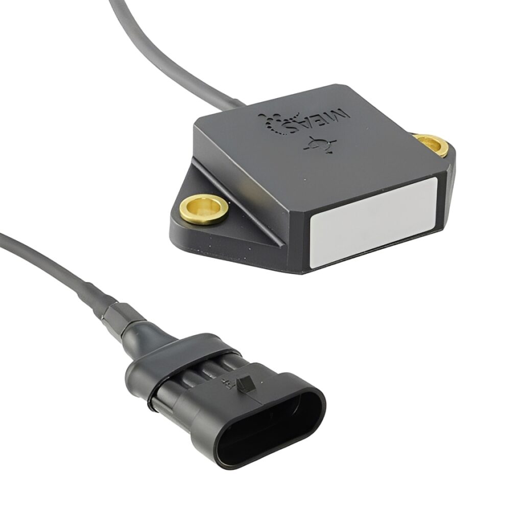
A sensor inclinometer measures angular tilt relative to gravity. It converts changes in inclination into a readable signal that controllers and microcontrollers can process for precise positioning. In electronics and industrial automation, it enables machines, tools, and structures to maintain alignment, improve safety, and reduce costly downtime.
How a Sensor Inclinometer Works
Inclinometers use gravity as a reference to detect pitch and roll. Common designs include capacitive MEMS, electrolytic, and fluid based cells. As the device tilts, internal elements shift, changing capacitance or resistance, which the circuitry translates into voltage, current, or digital data.
- MEMS capacitive cells sense minute deflections and output stable signals.
- Integrated microprocessors filter noise and linearize the response curve.
- Built in temperature compensation stabilizes readings across thermal changes.
- Output interfaces range from analog voltage to RS 485, CANopen, or SPI.
Core Components in Modern Sensors
Reliable inclinometer performance depends on the full signal chain, not just the chip. Thoughtful selection of supporting electronics raises accuracy and uptime.
- Cables with robust shielding minimize interference near motors and contactors.
- Connectors with proper IP ratings protect against oils, dust, and vibration.
- Fuses and switches isolate faults and enable safe commissioning.
- LEDs on the housing give quick visual status during installation and service.
- High quality capacitor networks improve filtering for stable measurements.
Types of Sensor Inclinometers
Choosing the right technology depends on accuracy targets, environment, and budget.
- Capacitive MEMS
- Compact, low power, suitable for controllers and laptops as test hosts.
- Good shock resistance and wide dynamic range.
- Electrolytic
- High resolution at low frequencies, useful for structural monitoring.
- Requires careful thermal management and stable mounting.
- Dual axis or three axis modules
- Measure pitch, roll, and sometimes yaw derived with sensor fusion.
- Pair well with microcontrollers for real time control loops.
Key Specifications That Matter
Reading a datasheet with the right lens helps you pick a device that performs in the field.
- Range and resolution
- Ensure the full motion envelope fits the rated degrees.
- Match resolution to control demands for smooth actuation.
- Accuracy and linearity
- Consider combined errors over temperature and life.
- Check typical vs maximum figures across the full range.
- Bandwidth and response time
- Fast systems like robotics need higher bandwidth.
- Slow structural tilt can use heavy filtering for stability.
- Output and supply
- Analog 0 to 10 V, 4 to 20 mA, or digital.
- Confirm compatibility with existing controller and I O.
- Environmental ratings
- Shock, vibration, and ingress protection for oils and dust.
- Thermal limits and condensation resistance.
Wiring, Mounting, and Safety
Careful installation ensures that the specified accuracy becomes real world performance.
- Use low noise cables with strain relief grips near connectors to reduce mechanical errors.
- Keep signal runs away from contactors, VFDs, and power lines to lower EMI.
- Add thermal pads between the housing and bracket when heat conduction improves stability.
- Apply thread locking oils only where specified to avoid contaminating seals.
- Route power through fuses and install accessible switches for safe lockout.
- Verify ground and shield strategy at one end to prevent loops.
Calibration and Commissioning
A quick, repeatable workflow protects project timelines and improves data trust.
- Mount the sensor on a rigid, flat surface aligned to the reference axis.
- Zero the reading at a known level position with software tools or hardware pins.
- Step through known angles and record deviations for controller compensation.
- Store calibration constants in non volatile memory on the microcontrollers or PLC.
Integration With Control Systems
Inclinometers fit naturally into modern electronics stacks that mix sensing and actuation.
- Pair with microprocessors for advanced filtering, sensor fusion, and diagnostics.
- Use controllers that support analog and digital inputs to simplify wiring.
- Enable alarms for out of range tilt to trigger safety interlocks and emergency stops.
- Log data to laptops during trials, then migrate to embedded storage after validation.
Applications Across Industries
Tilt data improves reliability, quality, and operator safety in diverse settings.
- Industrial machines
- Gantry alignment, conveyor leveling, and robotic end effector control.
- Construction and civil
- Crane boom monitoring and bridge settlement tracking over seasons.
- Mobility and medical
- Platform stabilization and patient bed angle control with smooth ramps.
- Renewable energy
- Solar trackers that use tilt feedback to optimize irradiance.
- Precision agriculture
- Implement leveling to protect soil and ensure uniform application.
Troubleshooting Signal Quality
Most performance issues trace back to a few repeatable causes.
- Unstable readings
- Check loose connectors, cable damage, or inadequate shielding.
- Add filtering in firmware and verify proper capacitor placement.
- Temperature drift
- Improve airflow or add thermal pads and insulation where needed.
- Enable the sensor’s internal compensation features.
- Offset errors after maintenance
- Re run the zero procedure on a verified level surface.
- Confirm that mounting screws are tightened with the right tools.
Selection Checklist for a Sensor Inclinometer
Use this quick list to move from shortlist to final part number with confidence.
- Define angle range, accuracy, and bandwidth targets in writing.
- Confirm environmental ratings for oils, dust, and wide thermal swings.
- Match outputs to PLCs, controllers, and available power rails.
- Review connector style, pinout, and cable length for the enclosure layout.
- Validate lifecycle needs with MTBF data and service access to switches and fuses.
- Plan spares and calibration intervals to uphold safety and quality goals.
Future Trends to Watch
The next generation of inclinometer designs will extend performance while simplifying integration.
- On sensor AI filters running on efficient microprocessors for adaptive noise control.
- Time synchronized multi sensor arrays that merge inertial and GNSS data.
- Smart connectors and self identifying cables that speed commissioning.
- Low power modes that extend battery life in mobile tools and compact devices.
Conclusion: Turn Tilt Data Into Action
A well selected sensor inclinometer delivers precise, stable angle measurements that make systems safer, smarter, and easier to maintain. By aligning specifications with real conditions, protecting wiring with the right cables and connectors, and integrating robust filtering on microcontrollers, teams gain accurate control without guesswork. Add thoughtful mounting, thermal management, and protective fuses and switches, and you will achieve repeatable results that scale from prototypes to production.